How does a fiber optic connection work?
Introduction
Have you seen technicians digging trenches in your street, installing green enclosures on building facades, or running cables along poles? These are the signs that a fiber optic connection is being deployed in your neighbourhood.
A fiber optic connection is a team effort that brings together civil engineering specialists, cable layers, fiber splicers, network technicians, and service activation agents. It can take from a few weeks to several months depending on the size of the project.
In this course, we will follow the complete path of the fibre, from the operator’s optical connection node (NRO) all the way to the wall socket at the subscriber’s premises.
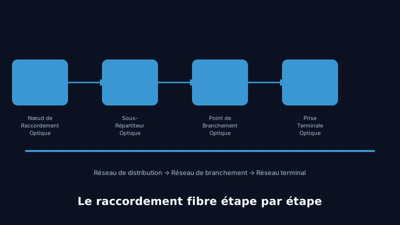
 Figure 1 — Complete FTTH network architecture: NRO → SRO → PBO → PTO
1. Overview of the FTTH network
1.1 The four network nodes
An FTTH network consists of four successive levels, each with a precise role:
| Acronym | Full name | Role | Location |
|---|---|---|---|
| NRO | Optical Connection Node | Signal source, OLT installed | Operator building, air-conditioned |
| SRO | Optical Sub-Distribution Node | Redistribution to neighbourhoods | Street cabinet, 200–500 m from NRO |
| PBO | Optical Branching Point | Last distribution level | Enclosure on façade or pole |
| PTO | Optical Terminal Socket | Subscriber-end connection | Interior wall socket |
1.2 The tree logic
Think of a tree: the NRO is the trunk, the SRO is a large branch, the PBO is a small branch, and the PTO is the leaf that reaches each dwelling. The fibre splits progressively through passive splitters (dividers that require no electricity) to serve more and more subscribers.
Concrete example: one NRO can feed several dozen SROs. Each SRO serves several hundred PBOs. Each PBO typically serves 4 to 16 subscribers. A single NRO can therefore cover several thousand homes.
2. Step 1: Civil engineering works
2.1 Planning and authorisations
Before anything is dug, the operator or its subcontractor must:
- Study the maps of existing underground networks (water, gas, electricity, telecoms)
- Submit a notice of intention to commence works to identify all underground networks
- Obtain road occupation permits from the municipality or local authority
- Notify residents (mandatory notice in Côte d’Ivoire)
Key takeaway: never dig without first verifying the presence of underground networks. Accidentally striking an electricity cable or a gas pipe can cause a serious accident.
2.2 Trench excavation
For underground cables, trenches are excavated according to precise rules:
- Width: between 20 and 40 cm depending on the number of conduits
- Depth: at least 50 cm in pavements, 60 cm in roadways
- Signage: cones, safety barriers, and DANGER signs are mandatory
2.3 HDPE conduits
Cables are not buried directly in the trenches. Conduits (HDPE — High-Density Polyethylene tubes) are installed first:
- Blue colour for telecommunications (CI standard)
- Internal diameter of 40 mm to 63 mm depending on the zone
- A warning tape in red-brown is laid 30 cm above the conduits
2.4 Pull pits (draw pits)
At regular intervals (every 50 to 100 metres), pull pits (inspection chambers) are installed. They allow technicians to access the conduits in order to:
- Pull cables through successive sections
- Perform joints if necessary
- Inspect and maintain the network
2.5 Façade and aerial installation
In certain areas, particularly in older neighbourhoods or rural zones, cables are not buried but are instead installed:
- On facades: fixed with clamps or collars on building walls
- Aerially: suspended between poles, with a metallic messenger wire to support the weight
3. Step 2: The distribution cable (NRO → SRO)
3.1 Characteristics of the distribution cable
The cable linking the NRO to the various SROs is the largest cable in the network. It contains a large number of fibres because it must feed many neighbourhoods:
| Capacity | Typical use |
|---|---|
| 48 to 72 fibres | Small residential neighbourhood |
| 96 to 144 fibres | Dense neighbourhood, medium-sized city |
| 288 to 432 fibres | Major urban artery, main road |
This cable is armoured: it contains steel wires or fibreglass reinforcement rods to withstand mechanical stress during pulling and throughout its service life on the ground (20 to 30 years).
3.2 Cable pulling
Pulling a cable through a conduit is done using a motorised or manual cable puller. The technique involves:
- First passing a pulling rod (thin, strong wire) through the conduit
- Attaching the cable to the pulling rod
- Pulling progressively, lubricating the cable if necessary
- Respecting the minimum bend radius (approximately 30 cm) to avoid breaking fibres
3.3 Splices at the NRO
Once the cable arrives at the NRO, the fibres are fusion-spliced to the ODF (Optical Distribution Frame) fibres. The ODF is the optical patching panel that organises connections between the active equipment (OLT) and the distribution cables.
Each splice must have a loss below 0.05 dB (fusion). Poor-quality splices are the primary cause of network faults.
3.4 The passive splitter at the SRO
At the SRO level, a passive splitter (also called an optical coupler) divides the signal into several sub-signals. For example, a 1:8 splitter transforms 1 incoming fibre into 8 outgoing fibres, each directed toward a different sector.
| Splitter type | Ratio | Optical loss |
|---|---|---|
| 1:2 splitter | 1 → 2 fibres | ~3.5 dB |
| 1:4 splitter | 1 → 4 fibres | ~7 dB |
| 1:8 splitter | 1 → 8 fibres | ~10.5 dB |
| 1:16 splitter | 1 → 16 fibres | ~13.5 dB |
| 1:32 splitter | 1 → 32 fibres | ~16.5 dB |
4. Step 3: The branching cable (SRO → PBO)
4.1 From the SRO to the PBO enclosure
The branching cable links the SRO to the various PBOs (Optical Branching Points) distributed throughout the neighbourhood. It is a more flexible, less bulky cable (generally 12 to 24 fibres) than the distribution cable.
4.2 Installing the PBO enclosure
The PBO is the enclosure commonly seen fixed to building facades, on poles, or sometimes in basement niches. It contains:
- A second level of splitter (1:4, 1:8, or 1:16)
- Trays for organising fibres
- SC/APC connectors for plugging in subscriber cables
Key takeaway: the PBO is the fibre “delivery point” for a building or group of houses. It is from this enclosure that the technician individually connects each subscriber.
4.3 Continuity check
After each section of the network, a continuity test is performed using an optical network detector (light tester). This simple test verifies that the fibre path is clear and that there are no breaks.
5. Step 4: The subscriber cable (PBO → PTO)
5.1 The drop cable
The cable linking the PBO to the terminal socket at the subscriber’s premises is called the drop cable or subscriber connection cable. Its characteristics:
- 2 fibres (one active, one spare)
- Flexible and lightweight
- UV-resistant outer jacket (for installation on facades)
- Typical length: 10 to 100 metres
5.2 Routing through the building
The cable can be installed in several ways depending on the building configuration:
- On the facade: fixed with clips or an external cable trunking up to the window or technical duct
- In the technical duct: in buildings with an existing telecoms duct
- Under skirting board: inside the dwelling, concealed under plastic skirting board
5.3 The optical terminal socket (PTO)
The PTO is installed inside the dwelling or office. It is a small wall box with:
- An SC/APC connector (green colour) to receive the patch cord toward the ONT
- A dust protection cover
- An engraved reference to identify the fibre
Important: the PTO must never be opened by the subscriber. It is the property of the operator.
6. Step 5: Service activation
6.1 Optical power measurement
Before activating the service, the technician measures the optical signal power at the PTO using an OPM (Optical Power Meter).
| Power level | Interpretation |
|---|---|
| -5 to -25 dBm | Excellent signal, perfect connection |
| -25 to -30 dBm | Acceptable signal, check connectors |
| Below -30 dBm | Insufficient signal, locate and correct the fault |
| No signal | Fibre break or incorrect connection |
6.2 OTDR measurement (optional)
For complex installations or in the event of a problem, an OTDR (Optical Time-Domain Reflectometer) can pinpoint exactly where a fault is located in the fibre. This measurement is more advanced and will be covered in a dedicated course.
6.3 Connecting the ONT
Once the optical power has been validated, the technician connects the ONT (Optical Network Terminal — also called the fiber box):
- An SC/APC patch cord links the PTO to the ONT
- The ONT connects to the Wi-Fi router via an RJ45 Ethernet cable
- Activation is triggered remotely by the operator (within a few minutes)
6.4 Service tests
At the end of the installation, the technician performs the final checks:
- Speed test: verification that the promised throughput is achieved (e.g. 100 Mbit/s, 1 Gbit/s)
- Latency test: verification that the response time is acceptable (< 10 ms on fibre)
- Phone test: if included in the service offer
- TV test: if included in the service offer
- Document handover: service activation form signed by the subscriber
7. Duration and cost of a connection
7.1 Typical duration per phase
| Phase | Average duration |
|---|---|
| Civil engineering (trenches, conduits) | 1 to 3 weeks depending on length |
| Distribution cable installation and splicing | 1 to 2 weeks |
| PBO enclosure installation | 3 to 5 days |
| Subscriber connection | 2 to 4 hours per dwelling |
| Service activation | 30 to 60 minutes per subscriber |
7.2 The teams involved
An FTTH connection mobilises several specialist teams:
- Civil engineering team: excavation, conduits, backfilling
- Cable pulling team: threading cables through conduits
- Splicing team: fibre fusion splices at the NRO, SRO, and PBO
- Subscriber connection team: drop cable, PTO, ONT
- Service activation team: testing, activation, documentation
8. Recap quiz
1. What does PBO stand for?
- a) Passive Base Optic
- b) Optical Branching Point
- c) Port of Base Optics
- d) Optical Patching Board
2. What is the minimum trench depth for fibre in a pavement?
- a) 20 cm
- b) 30 cm
- c) 50 cm
- d) 100 cm
3. A 1:8 splitter produces how many output fibres?
- a) 1
- b) 4
- c) 8
- d) 16
4. Which measurement is used to check signal power at the terminal socket?
- a) OTDR
- b) OPM (Optical Power Meter)
- c) VFL (Visual Fault Locator)
- d) BERT
Answers: 1-b, 2-c, 3-c, 4-b
Conclusion
A fiber optic connection is not a simple cable plug-in: it is a chain of precise operations requiring varied skills and rigorous organisation. Every step is critical — a poor-quality splice, a dirty connector, or an over-bent cable can degrade service quality for dozens of subscribers.
This is why technician training is essential. In Côte d’Ivoire, the fiber optics sector is actively recruiting to support the ongoing deployment in Abidjan and other major cities.
Estimated duration: 40 minutes · Level: beginner
Want to learn how to carry out a fiber optic connection yourself, from splicing to OTDR testing? Discover the certified fiber optic training courses offered by KMC in Abidjan.
Go further?
These free courses introduce the key concepts. Join a full certified programme at KMC in Abidjan to become a recognised fibre optic technician.
View certified programmesKMC Team
Training centre · Abidjan